6-gang 3 Phase 208/120v 1200 Amp Ringless Style Multi-family Metering

Three-phase transformer with four wire output for 208Y/120 volt service: 1 wire for neutral, others for A, B and C phases
Iii-phase electric power (abbreviated 3φ [i]) is a common type of alternating current used in electricity generation, transmission, and distribution.[2] It is a type of polyphase system employing 3 wires (or four including an optional neutral return wire) and is the near mutual method used by electrical grids worldwide to transfer power.
3-stage electrical ability was adult in the 1880s by multiple people. Iii-stage ability works by the voltage and currents being 120 degrees out of phase on the 3 wires. As an AC system it allows the voltages to be hands stepped up using transformers to loftier voltage for transmission, and dorsum downwardly for distribution, giving loftier efficiency.
A 3-wire three-phase circuit is unremarkably more than economic than an equivalent ii-wire single-phase circuit at the same line to ground voltage because information technology uses less conductor material to transmit a given amount of electric power.[3] Iii-phase power is mainly used directly to power large motors and other heavy loads. Small loads often utilize only a two-wire single-phase excursion, which may exist derived from a three-phase organization.
Terminology [edit]
The conductors between a voltage source and a load are called lines, and the voltage between any two lines is called line voltage. The voltage measured betwixt whatsoever line and neutral is called stage voltage.[4] For example, for a 208/120 volt service, the line voltage is 208 Volts, and the phase voltage is 120 Volts.
History [edit]
Polyphase power systems were independently invented by Galileo Ferraris, Mikhail Dolivo-Dobrovolsky, Jonas Wenström, John Hopkinson, William Stanley Jr., and Nikola Tesla in the late 1880s.[v]
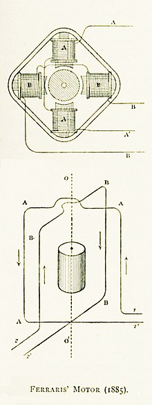
The first Air conditioning motor in the world of Italian physicist Galileo Ferraris. This was a two-phase motor and requires 4 wires, which is less efficient. three-phase motors and generators were developed by adding extra coils and connecting some of the wires
Three phase power evolved out of electric motor development. Ferraris independently researched the rotary magnetic field in 1885. Ferraris experimented with different types of asynchronous electric motors. The research and his studies resulted in the evolution of an alternator, which may be thought of as an alternate-current motor operating in contrary, so as to catechumen mechanical (rotating) power into electric power (every bit alternating electric current).
On 11 March 1888, Ferraris published his enquiry in a newspaper to the Royal Academy of Sciences in Turin
(Two months later Nikola Tesla gained U.Southward. Patent 381,968, awarding filed October 12, 1887. Serial Number 252,132. Effigy thirteen of this patent shows that Tesla envisaged his 3-phase motor being powered from the generator via six wires, indicating that at that fourth dimension he had non the concept of three-phase transmission over only three wires as developed past Mikhail Dolivo-Dobrovolsky and later demonstrated at the International Electro-Technical Exhibition of 1891.)
These alternators operated past creating systems of alternating currents displaced from i another in stage by definite amounts, and depended on rotating magnetic field for their operation. The resulting source of polyphase power soon institute widespread credence. The invention of the polyphase alternator is key in the history of electrification, as is the power transformer. These inventions enabled power to be transmitted by wires economically over considerable distances. Polyphase power enabled the use of water-power (via hydroelectric generating plants in large dams) in remote places, thereby assuasive the mechanical free energy of the falling h2o to be converted to electricity, which and so could be fed to an electric motor at whatever location where mechanical piece of work needed to be done. This versatility sparked the growth of power-manual network grids on continents effectually the globe.
Mikhail Dolivo-Dobrovolsky adult the three-phase electrical generator and a three-phase electrical motor (1888) and studied star and delta connections. The triumph of the three-phase three-wire transmission system was displayed in Europe at the International Electro-Technical Exhibition of 1891, where Dolivo-Dobrovolsky used this organization to transmit electric ability at the distance of 176 km with 75% efficiency. In 1891 he as well created a three-stage transformer and short-circuited (squirrel-cage) consecration motor.[6] [7] He designed the world's first three-phase hydroelectric ability constitute in 1891.
Principle [edit]

Normalized waveforms of the instantaneous voltages in a three-phase system in 1 bicycle with fourth dimension increasing to the right. The phase order is 1‑2‑iii. This cycle repeats with the frequency of the power system. Ideally, each stage'due south voltage, electric current, and power is offset from the others' by 120°.
![]()
Three-phase electric power manual lines
![]()
Three-phase transformer (Békéscsaba, Hungary): on the left are the primary wires and on the right are the secondary wires
In a symmetric three-phase power supply organization, 3 conductors each conduct an alternating current of the same frequency and voltage aamplitude relative to a mutual reference, but with a stage divergence of ane third of a wheel (i.e. 120 degrees out of stage) between each. The common reference is normally connected to basis and often to a current-carrying usher called the neutral. Due to the phase departure, the voltage on whatsoever usher reaches its peak at i 3rd of a wheel after one of the other conductors and 1 3rd of a cycle before the remaining conductor. This phase delay gives constant power transfer to a balanced linear load. It also makes it possible to produce a rotating magnetic field in an electrical motor and generate other stage arrangements using transformers (for example, a two stage system using a Scott-T transformer). The aamplitude of the voltage deviation between ii phases is (i.732...) times the amplitude of the voltage of the individual phases.

The symmetric three-phase systems described here are merely referred to as three-phase systems because, although it is possible to design and implement disproportionate iii-phase ability systems (i.e., with unequal voltages or phase shifts), they are not used in practise considering they lack the almost important advantages of symmetric systems.
In a 3-phase system feeding a balanced and linear load, the sum of the instantaneous currents of the three conductors is zero. In other words, the current in each conductor is equal in magnitude to the sum of the currents in the other ii, but with the opposite sign. The return path for the current in any phase conductor is the other two phase conductors.
Constant power transfer and cancelling stage currents are possible with any number (greater than one) of phases, maintaining the chapters-to-conductor material ratio that is twice that of single-stage ability. However, two phases results in a less shine (pulsating) current to the load (making smoothen ability transfer a challenge), and more than three phases complicates infrastructure unnecessarily.[viii]
Three-stage systems may have a fourth wire, mutual in low-voltage distribution. This is the neutral wire. The neutral allows three separate unmarried-phase supplies to be provided at a constant voltage and is commonly used for supplying multiple single-stage loads. The connections are bundled then that, equally far every bit possible in each group, equal power is drawn from each stage. Further up the distribution system, the currents are ordinarily well balanced. Transformers may be wired to accept a four-wire secondary and a three-wire primary, while allowing unbalanced loads and the associated secondary-side neutral currents.
Stage sequence [edit]
Wiring for the 3 phases is typically identified by colors which vary by state. The phases must exist connected in the right social club to attain the intended management of rotation of 3-phase motors. For case, pumps and fans exercise not work in opposite. Maintaining the identity of phases is required if two sources could be connected at the same fourth dimension; a direct interconnect between 2 unlike phases is a short circuit.
Advantages [edit]
Every bit compared to a unmarried-phase AC ability supply that uses two conductors (phase and neutral), a three-phase supply with no neutral and the same phase-to-ground voltage and current chapters per phase can transmit three times as much power using simply 1.5 times as many wires (i.east., three instead of ii). Thus, the ratio of capacity to conductor textile is doubled.[ix] The ratio of chapters to conductor textile increases to 3:i with an ungrounded three-phase and center-grounded unmarried-phase system (or 2.25:1 if both employ grounds of the same gauge as the conductors). This leads to college efficiency, lower weight, and cleaner waveforms.
Three-stage supplies have properties that make them desirable in electric ability distribution systems:
- The phase currents tend to abolish out one some other, summing to aught in the instance of a linear counterbalanced load. This makes it possible to reduce the size of the neutral conductor because it carries little or no current. With a counterbalanced load, all the phase conductors carry the same electric current and so tin can be the aforementioned size.
- Power transfer into a linear balanced load is constant. In motor/generator applications, this helps to reduce vibrations.
- Three-phase systems can produce a rotating magnetic field with a specified direction and constant magnitude, which simplifies the design of electric motors, as no starting circuit is required.
Most household loads are single-stage. In Due north American residences, 3-phase power might feed an apartment block, while the household loads are connected as single phase. In lower-density areas, a single stage might be used for distribution. Some high-power domestic appliances such as electric stoves and clothes dryers are powered by a separate phase arrangement at 240 volts or from two phases of a three phase organisation at 208 volts.
Generation and distribution [edit]
Animation of three-phase current
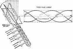

Left epitome: uncomplicated six-wire three-stage alternator with each stage using a separate pair of transmission wires.[ten] Right prototype: elementary three-wire three-phase alternator showing how the phases can share only 3 wires.[11]
At the power station, an electrical generator converts mechanical power into a set of 3 AC electrical currents, one from each whorl (or winding) of the generator. The windings are arranged such that the currents are at the same frequency but with the peaks and troughs of their wave forms start to provide three complementary currents with a phase separation of one-tertiary bike (120° or 2π⁄3 radians). The generator frequency is typically l or 60 Hz, depending on the country.
At the ability station, transformers change the voltage from generators to a level suitable for transmission in social club to minimize losses.
After further voltage conversions in the transmission network, the voltage is finally transformed to the standard utilization before ability is supplied to customers.
Most automotive alternators generate 3-phase Air conditioning and rectify it to DC with a diode bridge.[12]
Transformer connections [edit]
A "delta" connected transformer winding is continued betwixt phases of a iii-phase system. A "wye" transformer connects each winding from a stage wire to a mutual neutral point.
A single 3-phase transformer can be used, or iii single-phase transformers.
In an "open delta" or "V" system, only two transformers are used. A closed delta fabricated of three single-stage transformers tin can operate as an open delta if one of the transformers has failed or needs to be removed.[thirteen] In open delta, each transformer must behave current for its respective phases every bit well every bit electric current for the tertiary phase, therefore chapters is reduced to 87%. With 1 of 3 transformers missing and the remaining two at 87% efficiency, the capacity is 58% ( 2⁄iii of 87%).[14] [15]
Where a delta-fed organization must be grounded for detection of devious electric current to ground or protection from surge voltages, a grounding transformer (usually a zigzag transformer) may be continued to allow ground mistake currents to return from any phase to footing. Another variation is a "corner grounded" delta organization, which is a closed delta that is grounded at i of the junctions of transformers.[16]
3-wire and four-wire circuits [edit]

Wye (Y) and delta (Δ) circuits
There are two basic three-phase configurations: wye (Y) and delta (Δ). Every bit shown in the diagram, a delta configuration requires only three wires for transmission but a wye (star) configuration may accept a quaternary wire. The quaternary wire, if nowadays, is provided equally a neutral and is normally grounded. The 3-wire and iv-wire designations do not count the ground wire nowadays above many transmission lines, which is solely for mistake protection and does non carry electric current nether normal apply.
A 4-wire system with symmetrical voltages between phase and neutral is obtained when the neutral is connected to the "common star point" of all supply windings. In such a system, all three phases volition have the same magnitude of voltage relative to the neutral. Other non-symmetrical systems have been used.
The four-wire wye system is used when a mixture of single-stage and three-phase loads are to be served, such as mixed lighting and motor loads. An example of awarding is local distribution in Europe (and elsewhere), where each customer may be merely fed from one phase and the neutral (which is mutual to the iii phases). When a group of customers sharing the neutral depict unequal phase currents, the common neutral wire carries the currents resulting from these imbalances. Electrical engineers try to blueprint the three-phase power system for any one location so that the power drawn from each of iii phases is the same, equally far every bit possible at that site.[17] Electric engineers likewise effort to accommodate the distribution network so the loads are balanced as much every bit possible, since the same principles that apply to individual premises too apply to the wide-calibration distribution organisation power. Hence, every effort is made by supply government to distribute the power drawn on each of the three phases over a large number of bounds and so that, on average, as well-nigh as possible a balanced load is seen at the betoken of supply.
![]()
A delta-wye configuration across a transformer core (annotation that a applied transformer would usually have a different number of turns on each side).
For domestic use, some countries such every bit the UK may supply one phase and neutral at a loftier current (up to 100 A) to one property, while others such as Germany may supply 3 phases and neutral to each customer, merely at a lower fuse rating, typically xl–63 A per phase, and "rotated" to avoid the issue that more than load tends to exist put on the first stage.[ commendation needed ]
![]()
A transformer for a "high-leg delta" system used for mixed single-stage and three-phase loads on the aforementioned distribution system. Three-phase loads such as motors connect to L1, L2, and L3. Single-stage loads would be connected betwixt L1 or L2 and neutral, or betwixt L1 and L2. The L3 phase is ane.73 times the L1 or L2 voltage to neutral so this leg is not used for single-phase loads.
Based on wye (Y) and delta (Δ) connexion. Generally, in that location are four dissimilar types of three-phase transformer winding connections for transmission and distribution purposes.
- wye (Y) - wye (Y) is used for small-scale current and high voltage.
- Delta (Δ) - Delta (Δ) is used for big currents and depression voltages.
- Delta (Δ) - wye (Y) is used for step-upward transformers i.eastward., at generating stations.
- wye (Y) - Delta (Δ) is used for footstep-down transformers i.e., at the stop of the transmission.
In North America, a high-leg delta supply is sometimes used where 1 winding of a delta-connected transformer feeding the load is center-tapped and that center tap is grounded and continued as a neutral as shown in the 2d diagram. This setup produces 3 dissimilar voltages: If the voltage between the center tap (neutral) and each of the top and lesser taps (phase and anti-stage) is 120 V (100%), the voltage across the phase and anti-phase lines is 240 V (200%), and the neutral to "high leg" voltage is ≈ 208 V (173%).[thirteen]
The reason for providing the delta connected supply is unremarkably to power large motors requiring a rotating field. However, the bounds concerned volition too crave the "normal" North American 120 V supplies, two of which are derived (180 degrees "out of phase") between the "neutral" and either of the center tapped phase points.
Counterbalanced circuits [edit]
In the perfectly balanced case all iii lines share equivalent loads. Examining the circuits nosotros tin derive relationships betwixt line voltage and electric current, and load voltage and electric current for wye and delta connected loads.
In a counterbalanced organization each line will produce equal voltage magnitudes at phase angles equally spaced from each other. With Vi as our reference and Vthree lagging V2 lagging V1, using angle notation, and VLN the voltage between the line and the neutral nosotros accept:[18]

These voltages feed into either a wye or delta connected load.
Wye (or, star; Y) [edit]

Three-phase AC generator connected every bit a wye or star source to a wye or star connected load
The voltage seen by the load volition depend on the load connection; for the wye case, connecting each load to a stage (line-to-neutral) voltages gives:[18]
![{\displaystyle {\begin{aligned}I_{1}&={\frac {V_{1}}{\left|Z_{\text{total}}\right|}}\angle (-\theta ),\\[2pt]I_{2}&={\frac {V_{2}}{\left|Z_{\text{total}}\right|}}\angle \left(-120^{\circ }-\theta \right),\\[2pt]I_{3}&={\frac {V_{3}}{\left|Z_{\text{total}}\right|}}\angle \left(120^{\circ }-\theta \right),\end{aligned}}}](https://wikimedia.org/api/rest_v1/media/math/render/svg/cc5b2b2960f118272ac3e34043ab8220f7e3b41c)
where Z total is the sum of line and load impedances (Z full = Z LN + Z Y), and θ is the stage of the full impedance (Z total).
The phase angle divergence between voltage and electric current of each phase is non necessarily 0 and is dependent on the type of load impedance, Z y. Anterior and capacitive loads will cause current to either lag or lead the voltage. Still, the relative stage bending between each pair of lines (1 to ii, two to 3, and 3 to 1) will still be −120°.

A phasor diagram for a wye configuration, in which Vab represents a line voltage and Van represents a phase voltage. Voltages are balanced equally:
- Vab = (1∠α − 1∠α + 120°) √3 |V|∠α + 30°
- 5bc = √iii |V|∠α − 90°
- 5ca = √3 |V|∠α + 150°
(α = 0 in this case.)
By applying Kirchhoff's electric current law (KCL) to the neutral node, the three phase currents sum to the total current in the neutral line. In the balanced case:

Delta (Δ) [edit]

Iii-phase AC generator connected as a wye source to a delta-connected load
In the delta circuit, loads are connected across the lines, and so loads meet line-to-line voltages:[18]
![{\displaystyle {\begin{aligned}V_{12}&=V_{1}-V_{2}=\left(V_{\text{LN}}\angle 0^{\circ }\right)-\left(V_{\text{LN}}\angle {-120}^{\circ }\right)\\&={\sqrt {3}}V_{\text{LN}}\angle 30^{\circ }={\sqrt {3}}V_{1}\angle \left(\phi _{V_{1}}+30^{\circ }\right),\\[3pt]V_{23}&=V_{2}-V_{3}=\left(V_{\text{LN}}\angle {-120}^{\circ }\right)-\left(V_{\text{LN}}\angle 120^{\circ }\right)\\&={\sqrt {3}}V_{\text{LN}}\angle {-90}^{\circ }={\sqrt {3}}V_{2}\angle \left(\phi _{V_{2}}+30^{\circ }\right),\\[3pt]V_{31}&=V_{3}-V_{1}=\left(V_{\text{LN}}\angle 120^{\circ }\right)-\left(V_{\text{LN}}\angle 0^{\circ }\right)\\&={\sqrt {3}}V_{\text{LN}}\angle 150^{\circ }={\sqrt {3}}V_{3}\angle \left(\phi _{V_{3}}+30^{\circ }\right).\\\end{aligned}}}](https://wikimedia.org/api/rest_v1/media/math/render/svg/97c0c02e448dc7d255968fb031da1cb7491fd3ba)
(Φv1 is the stage shift for the first voltage, commonly taken to be 0°; in this case, Φv2 = −120° and Φv3 = −240° or 120°.)
Further:
![{\displaystyle {\begin{aligned}I_{12}&={\frac {V_{12}}{\left|Z_{\Delta }\right|}}\angle \left(30^{\circ }-\theta \right),\\[2pt]I_{23}&={\frac {V_{23}}{\left|Z_{\Delta }\right|}}\angle \left(-90^{\circ }-\theta \right),\\[2pt]I_{31}&={\frac {V_{31}}{\left|Z_{\Delta }\right|}}\angle \left(150^{\circ }-\theta \right),\end{aligned}}}](https://wikimedia.org/api/rest_v1/media/math/render/svg/40341769568f3f58a0c4288d44dc4f7e42353304)
where θ is the phase of delta impedance (Z Δ).
Relative angles are preserved, so I 31 lags I 23 lags I 12 by 120°. Computing line currents past using KCL at each delta node gives:

and similarly for each other line:
![{\displaystyle {\begin{aligned}I_{2}&={\sqrt {3}}I_{23}\angle \left(\phi _{I_{23}}-30^{\circ }\right)={\sqrt {3}}I_{23}\angle \left(-120^{\circ }-\theta \right),\\[2pt]I_{3}&={\sqrt {3}}I_{31}\angle \left(\phi _{I_{31}}-30^{\circ }\right)={\sqrt {3}}I_{31}\angle \left(120^{\circ }-\theta \right),\end{aligned}}}](https://wikimedia.org/api/rest_v1/media/math/render/svg/e41bd9b0412324f0224b1ae99bec6d5849a9f751)
where, again, θ is the phase of delta impedance (Z Δ).

A delta configuration and a respective phasor diagram of its currents. Phase voltages are equal to line voltages, and currents are calculated every bit:
- Ia = Iab − Ica = √3 Iab∠−xxx°
- Ib = Ibc − Iab
- Ic = Ica − Ibc
The overall power transferred is:
- S3Φ = 3VphaseI*stage
Inspection of a phasor diagram, or conversion from phasor annotation to circuitous note, illuminates how the difference betwixt two line-to-neutral voltages yields a line-to-line voltage that is greater by a factor of √3 . As a delta configuration connects a load across phases of a transformer, it delivers the line-to-line voltage divergence, which is √3 times greater than the line-to-neutral voltage delivered to a load in the wye configuration. As the power transferred is 52/Z, the impedance in the delta configuration must be 3 times what it would be in a wye configuration for the same power to exist transferred.
Single-stage loads [edit]
Except in a high-leg delta system and a corner grounded delta system, single-phase loads may be connected across any ii phases, or a load can be connected from phase to neutral.[19] Distributing single-stage loads amongst the phases of a 3-phase system balances the load and makes most economical use of conductors and transformers.
In a symmetrical three-phase four-wire, wye organisation, the 3 stage conductors have the same voltage to the system neutral. The voltage betwixt line conductors is √3 times the phase conductor to neutral voltage:[20]

The currents returning from the customers' premises to the supply transformer all share the neutral wire. If the loads are evenly distributed on all three phases, the sum of the returning currents in the neutral wire is approximately zero. Any unbalanced phase loading on the secondary side of the transformer volition use the transformer chapters inefficiently.
If the supply neutral is broken, stage-to-neutral voltage is no longer maintained. Phases with college relative loading volition feel reduced voltage, and phases with lower relative loading will experience elevated voltage, up to the phase-to-stage voltage.
A high-leg delta provides phase-to-neutral human relationship of V LL = 25 LN, all the same, LN load is imposed on one stage.[xiii] A transformer manufacturer'due south page suggests that LN loading not exceed five% of transformer chapters.[21]
Since √3 ≈ 1.73, defining 5 LN as 100% gives Five LL ≈ 100% × 1.73 = 173%. If V LL was ready equally 100%, then V LN ≈ 57.seven%.
Unbalanced loads [edit]
When the currents on the three live wires of a three-stage arrangement are not equal or are non at an exact 120° stage angle, the power loss is greater than for a perfectly counterbalanced system. The method of symmetrical components is used to analyze unbalanced systems.
Non-linear loads [edit]
With linear loads, the neutral merely carries the current due to imbalance between the phases. Gas-discharge lamps and devices that utilize rectifier-capacitor front end-end such equally switch-mode power supplies, computers, office equipment and such produce third-order harmonics that are in-stage on all the supply phases. Consequently, such harmonic currents add in the neutral in a wye system (or in the grounded (zigzag) transformer in a delta system), which can cause the neutral current to exceed the stage current.[xix] [22]
Three-phase loads [edit]
Iii-phase electric machine with rotating magnetic fields
An important form of three-phase load is the electrical motor. A iii-phase induction motor has a elementary design, inherently high starting torque and high efficiency. Such motors are applied in industry for many applications. A three-phase motor is more than compact and less costly than a single-phase motor of the same voltage class and rating, and single-phase Air-conditioning motors in a higher place xHP (vii.v kW) are uncommon. Three-phase motors also vibrate less and hence concluding longer than single-phase motors of the same ability used under the aforementioned conditions.[23]
Resistance heating loads such as electric boilers or space heating may be connected to three-stage systems. Electric lighting may too be similarly continued.
Line frequency flicker in calorie-free is detrimental to high speed cameras used in sports event broadcasting for slow motion replays. It can be reduced by evenly spreading line frequency operated light sources across the three phases so that the illuminated area is lit from all three phases. This technique was applied successfully at the 2008 Beijing Olympics.[24]
Rectifiers may use a three-phase source to produce a six-pulse DC output.[25] The output of such rectifiers is much smoother than rectified single stage and, dissimilar single-phase, does non drib to zero between pulses. Such rectifiers may be used for battery charging, electrolysis processes such as aluminium product or for operation of DC motors. "Zig-zag" transformers may make the equivalent of vi-phase total-wave rectification, twelve pulses per cycle, and this method is occasionally employed to reduce the cost of the filtering components, while improving the quality of the resulting DC.

One example of a three-phase load is the electric arc furnace used in steelmaking and in refining of ores.
In many European countries electric stoves are usually designed for a 3-stage feed with permanent connection. Private heating units are often connected between phase and neutral to allow for connection to a single-phase circuit if three-phase is not bachelor.[26] Other usual three-phase loads in the domestic field are tankless water heating systems and storage heaters. Homes in Europe and the Britain have standardized on a nominal 230 V between whatsoever stage and ground. (Existing supplies remain virtually 240 5 in the U.k..) Most groups of houses are fed from a three-stage street transformer then that individual premises with to a higher place-boilerplate demand tin be fed with a 2d or tertiary phase connexion.
Stage converters [edit]
Phase converters are used when three-stage equipment needs to exist operated on a single-phase ability source. They are used when three-phase power is not available or price is not justifiable. Such converters may also permit the frequency to be varied, allowing speed control. Some railway locomotives use a unmarried-phase source to drive iii-stage motors fed through an electronic drive.[27]
A rotary phase converter is a three-phase motor with special starting arrangements and power cistron correction that produces balanced three-phase voltages. When properly designed, these rotary converters can allow satisfactory operation of a three-stage motor on a unmarried-phase source. In such a device, the energy storage is performed past the inertia (flywheel outcome) of the rotating components. An external flywheel is sometimes found on one or both ends of the shaft.
A three-phase generator can be driven by a single-phase motor. This motor-generator combination can provide a frequency changer function as well equally phase conversion, but requires two machines with all their expenses and losses. The motor-generator method can also form an uninterruptible power supply when used in conjunction with a large flywheel and a battery-powered DC motor; such a combination will deliver nearly constant power compared to the temporary frequency drop experienced with a standby generator set gives until the standby generator kicks in.
Capacitors and autotransformers can be used to estimate a three-phase system in a static phase converter, but the voltage and phase angle of the additional phase may only exist useful for sure loads.
Variable-frequency drives and digital stage converters employ power electronic devices to synthesize a balanced 3-phase supply from single-phase input power.
Testing [edit]
Verification of the phase sequence in a circuit is of considerable practical importance. Two sources of three-stage power must not be connected in parallel unless they accept the same phase sequence, for example, when connecting a generator to an energized distribution network or when connecting two transformers in parallel. Otherwise, the interconnection will behave similar a curt circuit, and excess current will flow. The management of rotation of three-phase motors can be reversed past interchanging whatever two phases; it may be impractical or harmful to exam a machine past momentarily energizing the motor to observe its rotation. Phase sequence of two sources can be verified past measuring voltage between pairs of terminals and observing that terminals with very low voltage between them will take the same stage, whereas pairs that show a higher voltage are on unlike phases.
Where the absolute phase identity is not required, phase rotation exam instruments can exist used to identify the rotation sequence with one observation. The stage rotation test instrument may contain a miniature three-phase motor, whose management of rotation can be directly observed through the instrument example. Another design uses a pair of lamps and an internal phase-shifting network to display the phase rotation. Another type of instrument tin be connected to a de-energized 3-stage motor and can detect the small voltages induced by residue magnetism, when the motor shaft is rotated by hand. A lamp or other indicator lights to show the sequence of voltages at the terminals for the given direction of shaft rotation.[28]
Alternatives to iii-phase [edit]
- Split-phase electric power
- Used when three-stage power is non bachelor and allows double the normal utilization voltage to be supplied for loftier-power loads.
- Two-stage electric power
- Uses two AC voltages, with a xc-electrical-degree phase shift between them. Ii-stage circuits may be wired with two pairs of conductors, or ii wires may be combined, requiring only three wires for the circuit. Currents in the common conductor add to 1.four times the electric current in the private phases, so the mutual conductor must be larger. Two-phase and three-phase systems can be interconnected by a Scott-T transformer, invented past Charles F. Scott.[29] Very early AC machines, notably the first generators at Niagara Falls, used a 2-phase organisation, and some remnant two-phase distribution systems still exist, but three-phase systems have displaced the two-phase organisation for modernistic installations.
- Monocyclic power
- An asymmetrical modified 2-phase power system used by General Electrical around 1897, championed past Charles Proteus Steinmetz and Elihu Thomson. This organisation was devised to avoid patent infringement. In this arrangement, a generator was wound with a full-voltage unmarried-phase winding intended for lighting loads and with a modest fraction (usually ane/iv of the line voltage) winding that produced a voltage in quadrature with the main windings. The intention was to utilize this "power wire" additional winding to provide starting torque for induction motors, with the main winding providing ability for lighting loads. After the expiration of the Westinghouse patents on symmetrical two-phase and 3-phase power distribution systems, the monocyclic system vicious out of utilise; it was difficult to analyze and did not concluding long enough for satisfactory energy metering to be developed.
- Loftier-phase-society systems
- Have been built and tested for power transmission. Such transmission lines typically would use vi or twelve phases. High-phase-society manual lines allow transfer of slightly less than proportionately higher power through a given volume without the expense of a high-voltage direct current (HVDC) converter at each cease of the line. Still, they require correspondingly more than pieces of equipment.
- DC
- AC was historically used considering it could exist easily transformed to college voltages for long distance transmission. Nevertheless modernistic electronics can raise the voltage of DC with high efficiency, and DC lacks pare effect which permits transmission wires to exist lighter and cheaper and and then high-voltage direct current gives lower losses over long distances.
Color codes [edit]
Conductors of a 3-stage system are usually identified by a color code, to allow for counterbalanced loading and to clinch the correct stage rotation for motors. Colors used may adhere to International Standard IEC 60446 (later on IEC 60445), older standards or to no standard at all and may vary fifty-fifty within a single installation. For example, in the U.S. and Canada, different color codes are used for grounded (earthed) and ungrounded systems.
| Land | Phases[note 1] | Neutral, Northward[note 2] | Protective earth, PE[notation three] | |||||||||
|---|---|---|---|---|---|---|---|---|---|---|---|---|
| L1 | L2 | L3 | ||||||||||
| Commonwealth of australia and New Zealand (AS/NZS3000:2007 Figureiii.2, or IEC60446 equally canonical by Equally:3000) | Red, or brown[note 4] | White;[annotation 4] prev. yellow | Dark blue, or greyness[note 4] | Black, or bluish[note 4] | Dark-green/Yellow-striped; (Installations prior to 1966, Greenish.) | |||||||
| Canada | Mandatory[xxx] | Red[note 5] | Blackness | Blue | White, or grey | Dark-green mayhap yellow-striped, or uninsulated | ||||||
| Isolated systems[31] | Orange | Brown | Yellow | White, or grey | Green perchance yellow-striped | |||||||
| European CENELEC (European Union and others; since April 2004, IEC 60446, later IEC60445-2017), United Kingdom (since 31March 2004), Hong Kong (from July 2007), Singapore (from March 2009), Russian federation (since 2009; GOSTR50462), Argentine republic, Ukraine, Belarus, Kazakhstan, South Korea (from Jan. 2021) | Brown | Black | Greyness | Bluish | Green/yellow-striped[note 6] | |||||||
| Older European (prior to IEC 60446, varied by country)[note vii] | ||||||||||||
| United kingdom (earlier Apr 2006), Hong Kong (before April 2009), South Africa, Malaysia, Singapore (before February 2011) | Red | Yellow | Blue | Black | Green/yellowish-striped; before c. 1970, green | |||||||
| India | Red | Yellowish | Blueish | Black | Green mayhap yellow-striped | |||||||
| Chile - NCH 4/2003 | Bluish | Black | Red | White | Light-green mayhap yellow-striped | |||||||
| Old USSR (Russia, Ukraine, Kazakhstan; before 2009), People'south Commonwealth of China[annotation viii] (GB50303-2002 Section15.2.ii) | Yellow | Green | Ruby-red | Sky blueish | Green/yellow-striped | |||||||
| Norway (earlier CENELEC adoption) | Blackness | White/grey | Brownish | Blue | Yellow/light-green-striped; prev. xanthous, or uninsulated | |||||||
| United States | Common practise[note 9] | Black | Red | Blue | White, or grayness | Dark-green perchance yellowish-striped,[note ten] or uninsulated | ||||||
| Alternative exercise[note 11] | Brown | Orangish (delta[note 12]) | Yellow | Grayness, or white | Green | |||||||
| Violet (wye) | ||||||||||||
See likewise [edit]
- Industrial and multiphase power plugs and sockets
- International Electrotechnical Exhibition
- Mathematics of three-stage electric power
- Three-stage AC railway electrification
- Rotary phase converter
- Y-Δ transform
Notes [edit]
- ^ Many labelling systems exist for phases, some having boosted meaning, such as: H1, H2, H3; A, B, C; R, Due south, T; U, V, West; R, Y, B.
- ^ Likewise, grounded conductor.
- ^ Also, globe, or grounding conductor.
- ^ a b c d In Australia and New Zealand, active conductors can be any color except green/yellowish, green, yellow, black, or light blue. Yellow is no longer permitted in the 2007 revision of wiring code ASNZS 3000. European colour codes are used for all IEC or flex cables such as extension leads, appliance leads etc. and are equally permitted for use in building wiring per AS/NZS 3000:2007.
- ^ In Canada the loftier leg conductor in a high-leg delta system is always marked red.
- ^ The international standard green-yellow marker of protective-earth conductors was introduced to reduce the risk of confusion past color blind installers. Nigh 7% to 10% of men cannot clearly distinguish between red and dark-green, which is a particular business concern in older schemes where cherry marks a live conductor and dark-green marks protective earth or safety ground.
- ^ In Europe, there still exist many installations with older colors simply, since the early on 1970s, all new installations utilize green/yellow earth according to IEC60446. (Due east.grand. stage/neutral & earth, German: black/grey & cerise; French republic: greenish/scarlet & white; Russia: red/grey & black; Switzerland: blood-red/grayness & yellow or xanthous & red; Denmark: white/black & red.
- ^ Note that while Mainland china officially uses phase 1: yellow, phase two: greenish, stage three: blood-red, neutral: blue, basis: greenish/yellow, this is not strongly enforced and there is significant local variation.
- ^ See Paul Cook: Harmonised colours and alphanumeric marking. IEE Wiring Matters
- ^ In the U.S., a green/yellow striped wire may indicate an isolated ground.[ citation needed ] In most countries today, green/yellowish striped wire may only exist used for protective world (safety basis) and may never be unconnected or used for whatever other purpose.
- ^ Since 1975, the U.S. National Electrical Code has not specified coloring of stage conductors. It is common practice in many regions to identify 120/208V (wye) conductors equally black, ruby-red, and blueish, and 277/480V (wye or delta) conductors as brown, orangish, xanthous. In a 120/240V delta organization with a 208Five high leg, the high leg (typically B phase) is ever marked orangish, commonly A phase is black and C phase is either red or blue. Local regulations may improve the N.E.C. The U.S. National Electric Code has color requirements for grounded conductors, basis, and grounded-delta three-phase systems which result in one ungrounded leg having a college voltage potential to ground than the other two ungrounded legs.
- ^ Must be the high leg, if information technology is present.
References [edit]
- ^ Saleh, South. A.; Rahman, M. A. (25 March 2013). "The analysis and evolution of controlled 3φ wavelet modulated AC-DC converter". 2012 IEEE International Conference on Power Electronics, Drives and Energy Systems (PEDES): 1–half-dozen. doi:10.1109/PEDES.2012.6484282. ISBN978-1-4673-4508-8. S2CID 32935308.
- ^ William D. Stevenson, Jr. Elements of Power Arrangement Analysis Third Edition, McGraw-Loma, New York (1975). ISBN 0-07-061285-iv, p. two
- ^ Terrell Croft, Wilford Summers (ed), American Electricians' Handbook, 11th ed., McGraw Loma, 1987 ISBN 0-07-013932-6 folio 3-x effigy 3-23.
- ^ Brumbach, Michael (2014). Industrial maintenance. Clifton Park, NY: Delmar, Cengage Learning. p. 411. ISBN9781133131199.
- ^ "Ac Power History and Timeline". Edison Tech Center. Edison Tech Heart. Retrieved January 24, 2022.
- ^ Woodbank Communications Ltd.'s Electropaedia: "History of Batteries (and other things)"
- ^ Gerhard Neidhöfer: Michael von Dolivo-Dobrowolsky und der Drehstrom. Geschichte der Elektrotechnik VDE-Buchreihe, Volume 9, VDE VERLAG, Berlin Offenbach, ISBN 978-three-8007-3115-2.
- ^ von Meier, Alexandra (2006). Electric Power Systems. Hoboken, New Bailiwick of jersey: John Wiley & Sons, Inc. p. 160. ISBN978-0-471-17859-0.
We also stated ane rationale for this 3-phase system; namely, that a three-phase generator experiences a constant torque on its rotor as opposed to the pulsating torque that appears in a single- or two-stage machine, which is obviously preferable from a mechanical engineering standpoint.
- ^ Cotton fiber, H, Electrical Technology, 6th Ed., Pitman, London, 1950, p. 268
- ^ Hawkins Electric Guide, Theo. Audel and Co., 2nd ed., 1917, vol. 4, Ch. 46: Alternate Currents, p. 1026, fig. 1260.
- ^ Hawkins Electric Guide, Theo. Audel and Co., 2nd ed., 1917, vol. 4, Ch. 46: Alternating Currents, p. 1026, fig. 1261.
- ^ (PDF). August 30, 2017 https://web.annal.org/web/20170830033252/http://world wide web.rle.mit.edu/per/ConferencePapers/cpConvergence00p583.pdf. Archived from the original (PDF) on 2017-08-30.
- ^ a b c Fowler, Nick (2011). Electrician'southward Calculations Manual 2nd Edition. McGraw-Hill. pp. 3–5. ISBN978-0-07-177017-0.
- ^ McGraw-Hill (1920). "Three-Stage Power from Single-Phase Transformer Connections". Ability. 51 (17). Retrieved 21 December 2012.
- ^ H. Westward. Beaty, D.G. Fink (ed) Standard Handbook for Electric Engineers Fifteenth Edition, McGraw-Colina, 2007 ISBN 0-07-144146-eight, p. 10–11
- ^ "Schneider" (PDF).
- ^ "Saving energy through load balancing and load scheduling" (PDF). Archived from the original (PDF) on 2014-09-11. Retrieved 2014-08-03 .
- ^ a b c J. Duncan Glover; Mulukutla S. Sarma; Thomas J. Overbye (April 2011). Ability System Analysis & Design. Cengage Learning. pp. 60–68. ISBN978-one-111-42579-one.
- ^ a b Lowenstein, Michael. "The 3rd Harmonic Blocking Filter: A Well Established Approach to Harmonic Electric current Mitigation". IAEI Mag. Archived from the original on 8 September 2013. Retrieved 24 November 2012.
- ^ The boy electrician by J W Sims M.I.Due east.E. (Page 98)
- ^ "Federal pacific". Archived from the original on May thirty, 2012.
- ^ Enjeti, Prasad. "Harmonics in Low Voltage Iii-Phase Four-Wire Electrical Distribution Systems and Filtering Solutions" (PDF). Texas A&M University Power Electronics and Power Quality Laboratory. Archived from the original (PDF) on 13 June 2010. Retrieved 24 November 2012.
- ^ Alexander, Charles Yard.; Sadiku, Matthew N. O. (2007). Fundamentals of Electrical Circuits. New York, NY: McGraw-Loma. p. 504. ISBN978-0-07-297718-9.
- ^ Hui, Dominicus. "Sports Lighting – Design Considerations For The Beijing 2008 Olympic Games" (PDF). GE Lighting. Archived from the original (PDF) on 28 April 2015. Retrieved 18 Dec 2012.
- ^ Pekarek, Steven; Skvarenina, Timothy (November 1998). "ACSL/Graphic Modeller Component Models for Electrical Power Education". IEEE Transactions on Education. 41 (4): 348. Bibcode:1998ITEdu..41..348P. doi:ten.1109/TE.1998.787374.
- ^ "British and European practices for domestic appliances compared", Electrical Times, volume 148, page 691, 1965.
- ^ "Speeding-upwards Conventional Lines and Shinkansen" (PDF). Japan Railway & Send Review. No. 58: 58. Oct 2011.
- ^ Steve Sentry, "Motor Control Fundamentals", Cengage Learning, 2012, ISBN 1133709176, folio lxx
- ^ Brittain, J. E. (2007). "Electric Engineering Hall of Fame: Charles F. Scott". Proceedings of the IEEE. 95 (4): 836–839. doi:10.1109/JPROC.2006.892488.
- ^ C22.1-15—Canadian Electrical Code, Part I: Safety Standard for Electrical Installations (23rd ed.). Canadian Standards Association. 2015. Rule four–038. ISBN978-1-77139-718-6.
- ^ C22.1-15—Canadian Electrical Lawmaking, Part I: Safety Standard for Electrical Installations (23rd ed.). Canadian Standards Clan. 2015. Rule 24–208(c). ISBN978-i-77139-718-half-dozen.
External links [edit]
- AC Power History and Timeline
Source: https://en.wikipedia.org/wiki/Three-phase_electric_power
Post a Comment for "6-gang 3 Phase 208/120v 1200 Amp Ringless Style Multi-family Metering"